

Custom Y Strainer Design: Key Factors for Reliable Flow and Filtration
2026-11-17
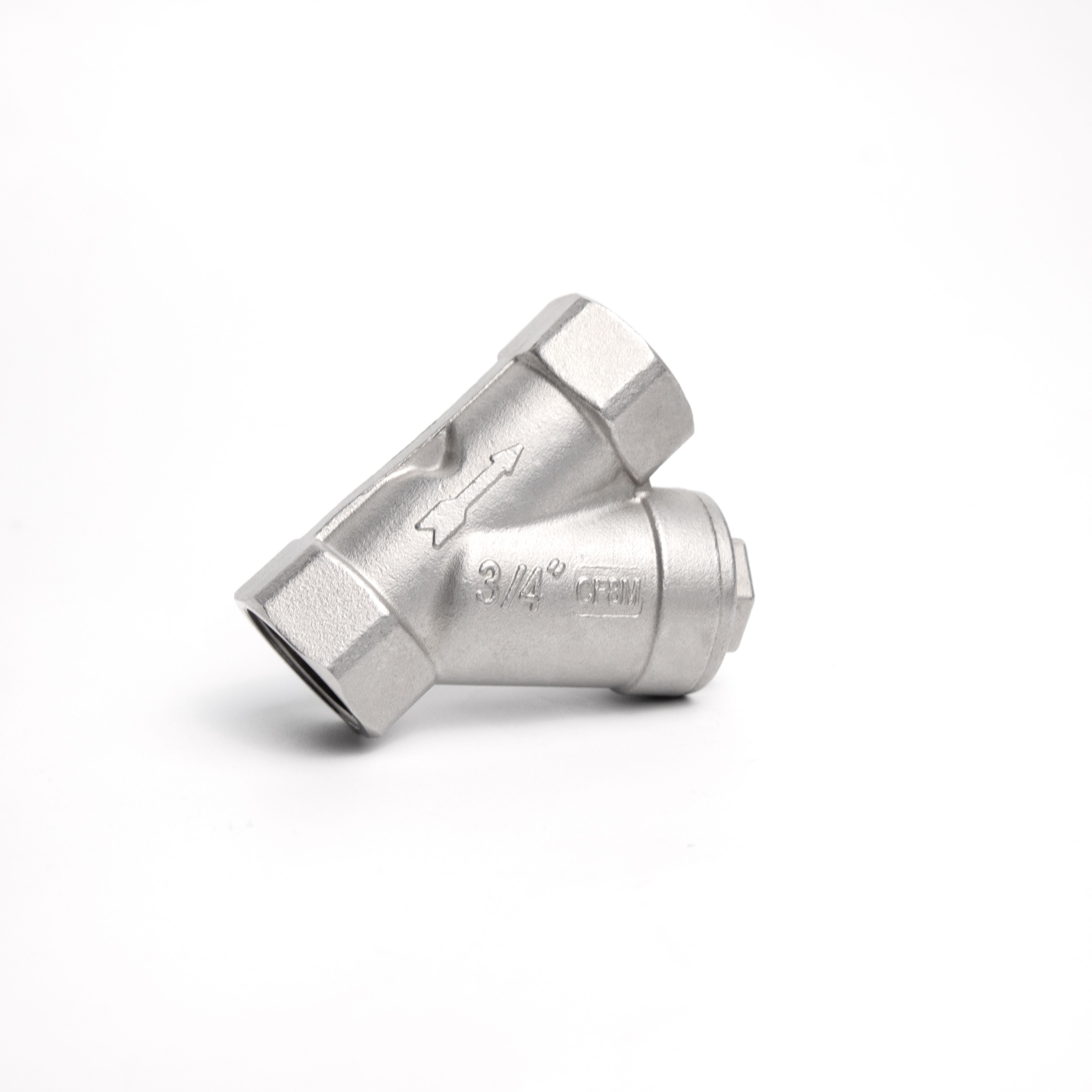
Industrial filtration often hides in plain sight, right where a single clogged strainer can throttle an entire process. Yet too many teams still treat a Y strainer as a stock item instead of a tailored flow-control component. In this guide, we break down the design choices that separate reliable filtration from recurring downtime. From open area ratio and screen opening to pressure drop and drain orientation, every factor matters. At UPTAI, we see custom Y strainers not as special requests, but as practical answers to real pipeline conditions. If you have ever wondered why a strainer works on paper but struggles in service, the next sections will give you a clearer path to specifying with confidence.
Where standard geometry meets real piping constraints
Piping design often looks straightforward on a schematic: lines run clean, elbows bend at exact angles, and branch connections sit where the drawing says they should. Real installations rarely cooperate. Supports land in awkward spots, existing steel leaves too little clearance, and the neat 90-degree turn that worked on paper collides with a beam someone forgot to mention. This is where standard geometry stops being a design tool and starts being a constraint you have to negotiate with.
The gap between nominal dimensions and field reality shows up in small, persistent ways. A flange rated for a certain pressure fits fine in a catalog, but add the bolt circle, the gasket, and the wrench clearance, and suddenly the spacing between two adjacent lines needs another half inch that isn't there. Pipe flexibility calculations assume a straight run between anchors, yet the actual routing has to jog around a cable tray or dip under a duct. These mismatches aren't errors; they're the normal condition of building in tight industrial spaces.
Working within those limits means treating geometry as a starting point rather than a fixed answer. Sometimes that means rotating a tee a few degrees to buy room for a valve handwheel. Other times it means accepting a slight slope that isn't ideal on paper but keeps the line serviceable. The goal is rarely a perfect model—it's a layout that respects the rules of standard components while still fitting the irregular, imperfect space where the pipe actually has to live.
Choosing the body material before the coating conversation
The decision about what the body will be made of usually gets settled long before anyone starts talking about coatings. Steel, aluminum, carbon fiber, even magnesium each bends, heats, and ages differently under real driving conditions. If the material choice is rushed, the coating conversation later becomes a series of compromises: uneven adhesion on complex curves, microfractures near welds, or fading that appears first along the sharpest edges. A calm early evaluation of how the metal or composite behaves under stress saves more time than any premium clearcoat can buy back.
Once the base material is fixed, attention shifts to its surface personality. Aluminum carries a thin oxide layer that plays tricks with primers if ignored. Steel may arrive with mill scale or light rust patterns that demand a specific preparatory step. Carbon fiber panels distort slightly with temperature swings, so the coating needs enough elasticity to follow those micro-movements without cracking. Knowing these quirks before any coating sample is sprayed means the conversation starts with the body's own voice rather than against it.
There is also the practical matter of repair and long-term care. A material that dents easily might force a thicker, more flexible film, while a stiff composite can accept a lighter, harder coating. If the owner lives near salt air or rough winter roads, the body material's corrosion behavior becomes the quiet factor that decides whether the coating system lasts five years or fifteen. Choosing the body material with intent gives the coating a fair chance to do what it was actually designed for.
Screen selection beyond a single mesh count
Mesh count gets quoted like it is the full specification, but it only tells part of the story. Two screens with the same count can have very different open areas because wire diameter and weave style change the real passage size. A heavier wire tightens the opening and leaves less free area, so the same nominal mesh can hold back more material or slow the flow. Checking wire diameter, aperture, and open area alongside the count gives a more honest starting point.
Beyond the numbers, what actually passes through and what stays behind depends on how the material loads and clears the screen. Some materials wedge, cling, or build up at the edges of the openings even when the aperture appears large enough. In those cases, shifting wire diameter or weave pattern can do more than jumping to a different count. A slightly more open construction with the right wire surface often improves flow without losing the cut or edge definition.
Tension and wear are easy to overlook in the selection stage, but they change the opening shape over time. A screen that is loose or unevenly tensioned lets material through where it should not, or distorts fine lines and edges. Checking wear points and tension loss after a short run usually reveals whether the real issue is the mesh count or the support and setup around it.
Pressure loss calculations that reflect fouling, not just clean water
Clean-water pressure loss figures are convenient, but they describe a system that stops existing the moment it is put into service. A thin biofilm or scale layer can reduce effective diameter and raise surface roughness enough to shift a pump curve, increase energy draw, and disturb balancing valves that were set from spotless baseline data.
Calculations should start with expected fouling factors and simulate the system after months of operation, not just at commissioning. That means using aged roughness coefficients, narrower effective diameters, or adjusted minor loss values for strainers, heat exchangers, and narrow passes where deposits collect first. The goal is to make the design point honest enough that performance stays within control range without constant manual rebalancing.
A common mistake is treating fouling as a flat safety margin added at the end. That hides where pressure loss actually grows and can lead to oversized pumps that waste energy in early life. Better calculations show two clear operating bands: clean-condition pressure and fouled-condition pressure, with setpoints and maintenance triggers tied to the difference.
Access and drainage details that reduce downtime
Most unplanned downtime doesn't begin with a breakdown; it begins with a seized drain plug, a panel that needs two people to remove, or a sump buried behind unrelated equipment. Access details decide whether a routine check takes ten minutes or half a shift. Drop-down covers, hatches placed at working height, and removable side panels that don't require disassembling surrounding components all keep maintenance from turning into an extended stoppage.
Drainage design matters just as much once the system is open. A sloped floor, an outlet sized for actual flow, and valves that operate cleanly with a gloved hand let fluids leave the machine quickly and completely. When washdown water, oil, or condensation pools in low spots, it accelerates corrosion and contamination, which stretches out the next service interval. Positioning the drain at the true lowest point and keeping the valve handle visible at a glance shorten the time needed to bring the equipment back online.
Field conditions are rarely clean or well-lit, so small mechanical choices carry real weight. Bolts that corrode, threads that gall, and conduits routed across a drain all add friction to a service call. Swapping a few fasteners for cam-lock covers, adding a raised guard rim around a drain outlet, or moving wiring away from removable panels may not show up in spec sheets, but these details remove the repeated small delays that eventually become costly downtime.
Testing the assembled unit under uneven flow
When a pump or valve assembly leaves the bench, its performance data usually comes from steady, even flow conditions. Real installations rarely behave that way. Uneven flow arrives from elbows placed too close to the inlet, partially closed upstream valves, or poorly matched pipe diameters. Testing the assembled unit under these distorted profiles reveals weaknesses that standard curves miss.
During the test, technicians deliberately throttle one branch of the supply manifold or insert a baffle upstream to create a lopsided velocity distribution. The unit may start to vibrate at a frequency that matches the blade-pass rate, or the suction pressure gauge may swing more than a few percent. In some cases, the noise changes from a steady hiss to a rhythmic thumping, and temperature sensors on the casing show a hot spot on the side facing the faster stream.
The goal is not to make the uneven flow go away but to find out how much distortion the assembly can tolerate before efficiency drops or cavitation sets in. Adjusting the inlet geometry, adding a flow straightener, or moving a sensor port are common outcomes of these tests. After each modification, the same uneven profile is repeated to confirm whether the vibration and temperature swings stay within acceptable limits.
FAQ
Flow characteristics and debris size matter most. Knowing velocity, viscosity, and the smallest particle you need to catch helps set the screen opening, screen area, and body size without causing excessive pressure loss.
More open area generally lowers pressure drop and extends the time between cleanings, but the screen still has to survive the differential pressure. Very fine mesh may need a perforated backing or thicker construction so it does not collapse or tear.
The blowdown chamber should sit in a position where solids can settle into it. If the pocket is mounted upside down or at an awkward angle, debris can stay in the flow path instead of collecting where it can be removed.
It depends on the fluid. Chloride-bearing streams may require duplex stainless, Hastelloy, or titanium. Abrasive slurries often benefit from hardened coatings or liners, and gasket and screen materials need to match the chemical and temperature conditions.
Use a quick-opening cover, provide enough blowdown connection size, and design the screen so it lifts out easily. If cleaning is difficult on site, operators may postpone service, which leads to high pressure drop or screen damage.
Yes, but the design has to account for higher gas velocity, possible entrained droplets, and tighter pressure drop limits. More screen area is often required, blowdown may need automation, and all materials and welds must meet the pressure and temperature rating.
It is a primary constraint. Pressure loss through the body and screen affects pump energy, NPSH margin, or compressor performance. A realistic design usually starts with a maximum clean pressure drop and leaves room for some fouling before the screen must be cleaned.
Perforated plate is usually better with hard or fibrous particles and whenever the screen needs extra strength. It resists tearing and crushing better than fine mesh. For very fine filtration, mesh can still be used but is often supported by a perforated backing.
Conclusion
Custom Y strainers usually fail less from a simple mesh choice and more from trying to force standard geometry into a piping layout that has its own constraints. Odd nozzle angles, tight clearances, and short straight runs affect how the body is oriented, supported, and drained long before the screen is selected. Material choice deserves attention ahead of any coating discussion because a stainless or high-alloy body changes thermal growth, flange loading, and corrosion allowance in ways no paint system can match. Screen specification also has to move beyond a single mesh count. A fine mesh that looks right on paper can blind quickly or collapse under intermittent solids unless the open area, perforated backing, and wire diameter are matched to the actual dirt load.
Pressure loss calculations built on clean water tell a misleading story once a unit is in service. A more honest approach adds a fouling allowance tied to expected particle size and loading so the differential pressure at cleaning time is known before startup. Access and drainage details then separate a quick maintenance task from a bypass operation. Blowdown connections, drain ports, and cover clearance should let an operator pull the screen without fighting the surrounding pipe rack. It is also worth testing the assembled strainer under uneven flow rather than relying on uniform bench conditions. Offset velocity, cycling flow, and partial screen blockage expose weak points in bracing and sealing that idealised tests miss.
Contact Us
Contact Person: Adonis
Email: [email protected]
Tel/WhatsApp: 8615858822657
Website: https://www.uptaivalve.com